36+ water level controller block diagram
BLOCK DIAGRAM P0wer supply transistor bc548 ic555 bc548 transistor Relay In 4007 diode switch Ac Motor 230v Water tank 4. The block diagram of the proposed control system design is shown in.

1 Automatic Water Level Controller Circuit Diagram Water Pumps Water Level Switch
Submitted by shriyash patil on.
. You can edit this. Flexible Automatic Water Level Controller and Indicator Water is very precious for the living beings. The water level controllers circuit diagram is shown in the image below.
21 BLOCK DIAGRAM DESCRIPTION As shown. 5 Circuit diagram for the three mode controller 11 6 Block diagram for a the proportional controller b the proportional plus reset controller and c the three mode controller 18 7. The block diagram of a typical industrial control system is shown in Fig 11.
As shown in above figure the full capacity of tank is 50 later. Download scientific diagram Block diagram of water level controller from publication. Initially controller displays the set.
MOV P211111111B initiates P2 as sensor input MOV P011111111B. Water sensing is accomplished. In a process Figure 11.
To program Arduino for water level controller. A prototype of water level control system has been built and implementations of. However we are utilising an 8051 microcontroller to construct a circuit that detects and controls the water level in an overhead tank automatically.
MOV P211111111B initiates P2 as sensor input. Puri cation chemical pulp and paper production and food production. Water Tank Assembly Block Diagram.
We require the detection of a water level in a tank. The circuit diagram of the water level controller is shown in the figure below. The working of the complete water level indicator project is shown in below block diagram.
Ad Float switches Relays contactors. In this post we will create the water level detector block diagram. The set point required level is fixed at 35 letters.
Specializing In Producing Mercury Relays And Other Mercury Related Products. Use Createlys easy online diagram editor to edit this diagram collaborate with others and export results to multiple image formats. Water level controller using 8051 Program.
Then we use the water level to control when to shutdown a.

Automatic Water Tank Level Controller Electrical Engineering Blog Electronics Circuit Electronic Schematics Electronic Circuit Projects
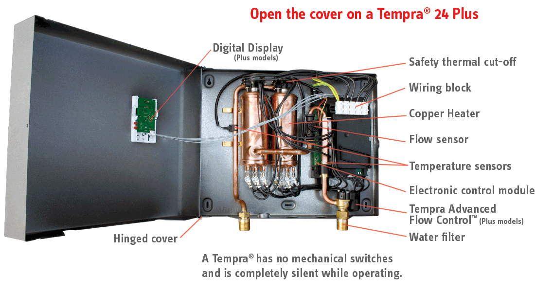
Tempra Whole House Tankless Electric Water Heaters Stiebel Eltron
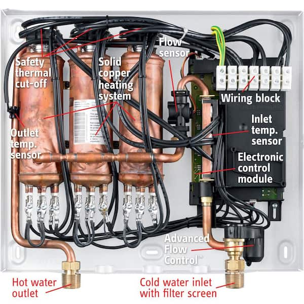
Stiebel Eltron Tempra 36 Plus Advanced Flow Control Self Modulating 36 Kw 7 03 Gpm Compact Residential Electric Tankless Water Heater Tempra 36 Plus The Home Depot
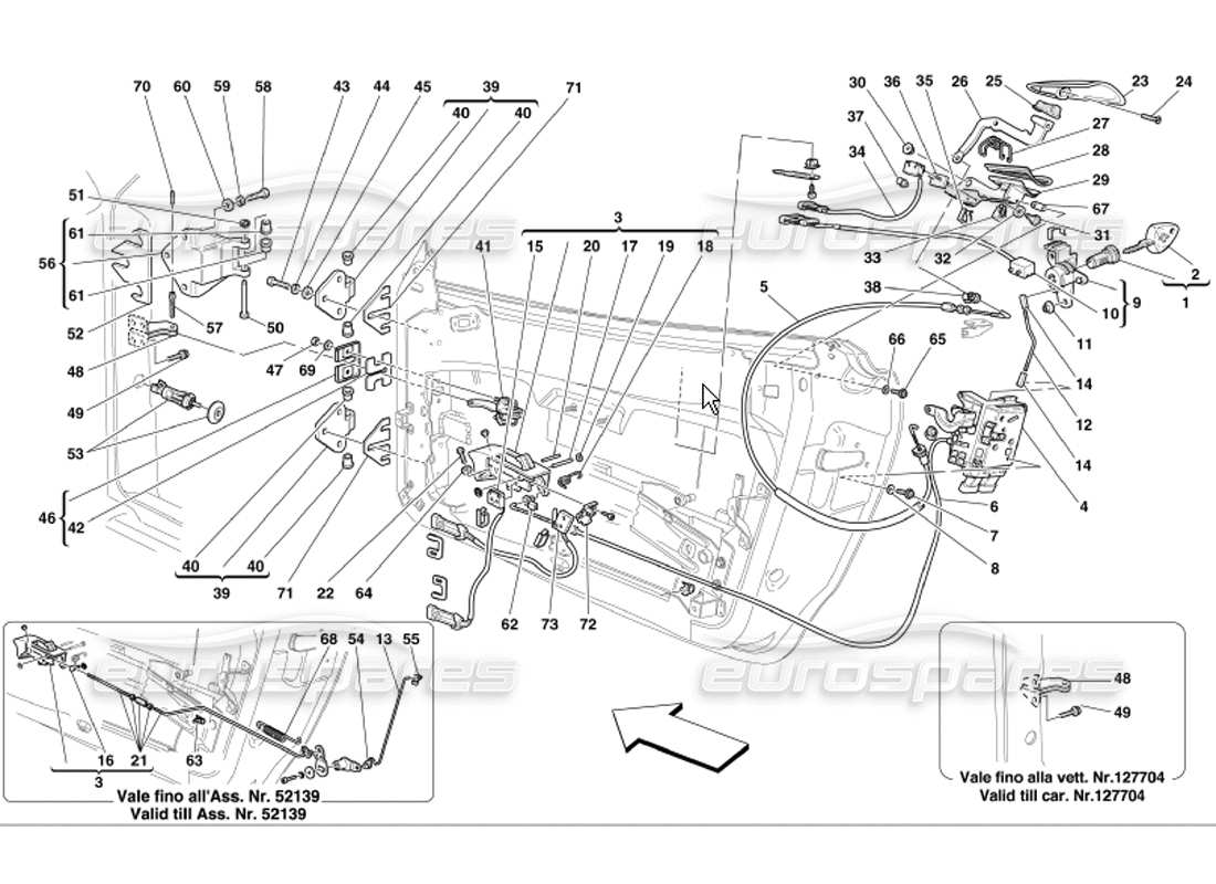
Eurospares Ferrari 360 Modena 117 Doors Opening Control And Hinges
2
Harvesting 62 Zn From An Aqueous Cocktail At The Nscl New Journal Of Chemistry Rsc Publishing Doi 10 1039 D0nj04411c
Class Definition For Class 137 Fluid Handling

Automatic Water Level Controller 2 Circuits Choice Eleccircuit Com Electronic Circuit Design Circuit Diagram Electronic Circuit Projects
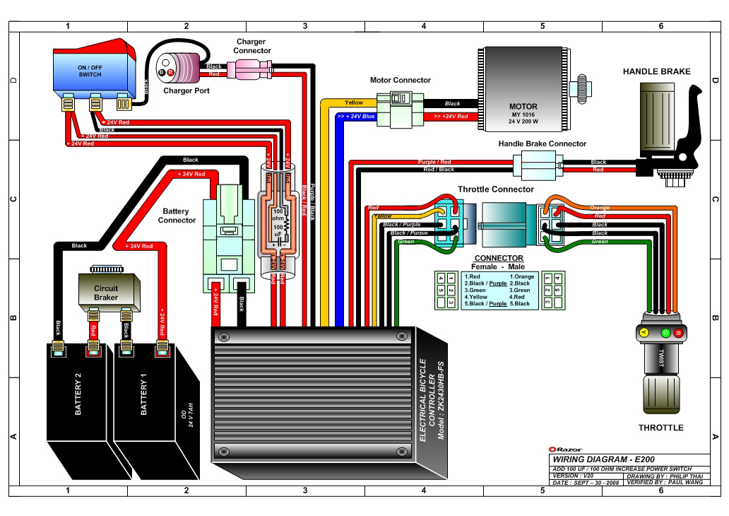
Razor E200 And E200s Electric Scooter Parts Electricscooterparts Com
Energies September 2018 Browse Articles
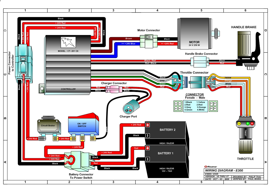
Razor E300 And E300s Electric Scooter Parts Electricscooterparts Com
2

We Have A 36 Volt E Z Go And It Stopped Running It Is Fully Charged But We Think It Could Be A Fuse Not Having A

Water Level Controller And Indicator Using 8051 Microcontroller Microcontrollers Electronics Projects Circuit Diagram

Hitachi Zh 210 6 210lc 6 Hybrid Excavator Electrical Hydraulic Circuit Diagram By Heydownloads Issuu

Numeric Water Level Indicator Liquid Level Sensor Circuit Diagram With 7 Segment Display Engineering Proj Circuit Diagram Level Sensor Electronic Schematics

555timer Based Water Level Controller Electronic Circuit Design Electronics Circuit Circuit Design